Building a Line Following Buggy
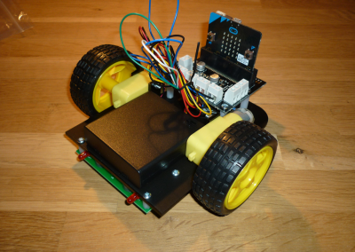
In this project we build a line-following buggy with 2 electric motors, and program the micro:bit to make the buggy follow a dark line on a light background.
You’ll need:
- A micro:bit
- A Kitronic Line-following Buggy kit:
https://www.kitronik.co.uk/5604-line-following-buggy-for-the-bbc-microbit.html - A large sheet of light-coloured paper and a thick dark marker (or dark tape) to make a course for the buggy to follow.
These instructions assume that all the soldering required has already been done. For full instructions, including soldering, go here: https://www.kitronik.co.uk/blog/bbc-microbit-line-following-buggy/
Once you’ve build the buggy, learn how to code it to make it move:
- micro:bit Line Following Buggy Code
- micro:bit Radio-controlled Buggy

1. Build the Buggy
Make sure you have all the components and tools you need:
Components
- chassis board
- 2 x wheels
- battery pack and 3 AA batteries
- fixings for circuit board
- circuit board
- motor driver board
- fixing for motor driver board
- 2 x drive motors
- driver motor mounting
- caster and stand-off
Tools
- a flat head screwdriver
- a cross head screwdriver

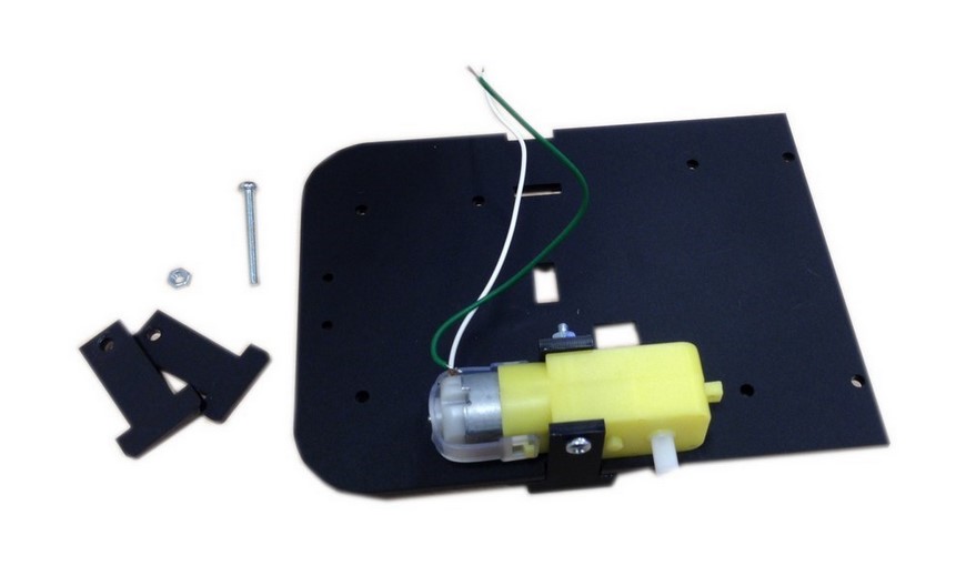
Attach the Motors
Take two of the ‘T’ shape acrylic pieces, push one through the bottom of the board (the top of the board is engraved with the word top) and align the other one up the notch in the edge of the body of the buggy.
Place the Motor 1 (green and white wires) between the two pieces with the motor terminals pointing toward the rounded corners of the buggy and the axle pointing outwards. Ensure that the motor is placed on the top side of the board.
Push a M3 30mm Pozi Pan Machine Screw through the holes in the ‘T’ pieces and motor to secure it in place, and then fasten it with the M3 Full Width nut.
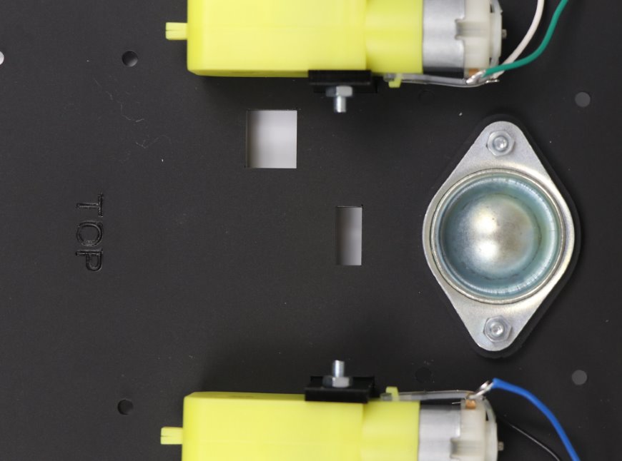
Repeat this for Motor 2 (blue and black) on the opposite side of the buggy.
Leave the wheels off for now as it will make it easier to add the rest of the components.
Attach the Caster
To attach the caster to the buggy, on the side marked top, place the provided acrylic spacer so that it lines up with the caster holes to the rear of the board. Place the caster so that the ball pokes through to the underside of the board.
Fix the caster in place using the 2 x 12mm M3 Machine Screws and 2 x M3 Full Width nuts.
Attach the Motor Driver Board
Attach the plastic spacers using four of the 6mm screws from underneath as shown above.
Attach the Motor Driver Board to the top of the M3 20mm Plastic Spacers using the M3 6mm Machine Screws. Make sure the terminal blocks are facing the centre of the board.
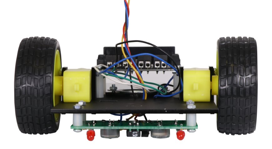
Attach The Line Following Board To The Buggy
Placing the 4 x plastic Hex M-F Standoffs between the chassis and the line following board, attach the line following board to the bottom of the chassis with the red LEDs pointing out from under the front of the buggy. Use 4 x M3 screws to fix the line following board to the Standoffs and 4 x M3 Full Width Nuts to secure the chassis to the Standoffs. Feed through the four wires from the Line Following Board through the hole in the middle of the chassis of the buggy.
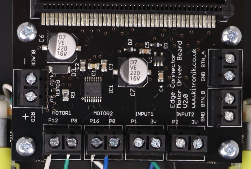
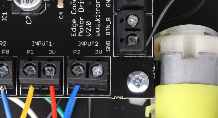
Connect The Wires To The Motor Driver Board
Connect the wires from the Line Following Board into the terminals on the Motor Driver Board for the BBC microbit as follows:
- ‘Out 1’ (Blue) goes into ‘INPUT2 – P2’ terminal.
- ‘Out 2’ (Yellow) goes into ‘INPUT1 – P1’ terminal.
- ‘+v’ (Red) goes into ‘INPUT1 – 3V’ terminal.
- ‘0v’ (Black) goes into ‘GND’ terminal.
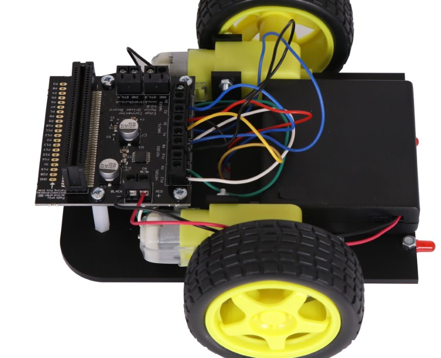
Attach The Battery Box
Using the sticky pad, attach the battery pack to the top of the buggy chassis with the switch poking through the rectangular cut-out.
Attach the red and black wires into the terminal on the Motor Driver Board for the BBC microbit labelled ‘POWER’. Put the black wire in the left hand side of the terminal labelled ‘BLACK’ and the red wire in the right hand side of the terminal labelled ‘RED’.
2. Test Code
Before going any further, let’s test the buggy using a short program. We’ll see how this works a little later. Type in the code below, check it, save it, and then flash to a micro:bit. You can do this with the micro:bit still attached to the buggy (switched off) if you have a long enough USB lead. If not, detach the micro:bit, flash the code and then re-attach.
This short piece of code drives the buggy forward for 5 seconds, then stops.
# Test buggy motors
# Richard 21/09/2017
# Test basic buggy motor functions by driving ahead and then stopping

# Import microbit libraries
from microbit import *

# Show an arrow
display.show(Image.ARROW_N)

# Set both motors to forward
pin8.write_digital(0)
pin12.write_digital(1)
pin0.write_digital(0)
pin16.write_digital(1)

# Run the motors for 3 seconds (5000 milliseconds)
sleep(3000)

# Set both motors to coast to a stop
pin8.write_digital(0)
pin12.write_digital(0)
pin0.write_digital(0)
pin16.write_digital(0)